

A crusher housing can lose its attachment when internal threads strip even though its bolts remain below their verified tensile capacity. I specify threaded connections by examining the complete mating system: usable engagement, material resistance, seating, and service load. This article explains how to distinguish nominal hole depth from effective engagement, prevent blind-hole false seating, and validate failure capacity in machinery housings, vehicle brackets, and hydraulic-equipment supports.
Threaded engagement converts rotational assembly motion into axial displacement and transfers tensile force between the external and internal thread flanks. After the head seats, continued controlled rotation stretches the bolt and compresses the connected stack. The mating threads must react that tension without stripPing, excessive deformation, or damage to the surrounding component. Bolt strength is therefore only one limit within a larger structural system.
The load is not distributed equally among all engaged turns. Elastic deformation of the bolt and mating component produces a nonuniform distribution, usually concentrating demand near the loaded end of the engagement. Thread geometry, stiffness, material response, and local yielding affect that distribution. Counting visible turns cannot replace a capacity assessment, especially when the mating component is weaker or more compliant than the bolt.
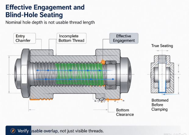
Effective engagement is the usable overlap of correctly formed external and internal threads that can carry load in the installed position. Entry chamfers, incomplete threads, damaged flanks, and portions beyond the actual overlap do not provide equivalent capacity. The full drilled depth of a blind hole is not its usable threaded depth. The full tapped depth is also not automatically the installed engagement if the bolt stops short or seats elsewhere.
A blind-hole bolt must clamp the members before its tip reaches an obstruction. If the tip contacts the bottom first, further torque can load the tip and threads while the head fails to develop the intended compression. Trapped fluid or debris can add resistance and may damage the hole or distort assembly evidence. Seating, engagement, and bottom clearance are distinct checks; passing one does not establish the others.
Under service tension, the engaged flanks transfer the bolt force into the Nut or tapped body. Under eccentric loading, that transfer can combine with bolt bending and uneven contact. Under impact, a loose joint can cycle between contact states and progressively damage the loaded threads. A specification must therefore connect engagement capacity to the actual installed preload and service load path.
No approved technical standards were supplied, so this article does not introduce a standard number, certification, issuing body, or numerical engagement rule. Verify thread geometry, material properties, dimensional tolerances, and acceptance criteria against the manufacturer's current test report and the project's approved design basis before specification.
I inspect both geometry and material condition at the mating interface. A nominally compatible thread can still fail through damaged flanks, insufficient usable length, local softness, or inadequate supporting wall thickness. The table identifies the component information needed to turn a thread callout into a validated connection.
| Component | MaterialSpec | Function | Failure Risk if Compromised |
|---|---|---|---|
| External-Threaded Bolt | Verify alloy, heat treatment, strength, thread geometry, and surface condition from current reports. | Carries tension and transfers it into engaged internal-thread flanks. | Tensile fracture, external-thread stripping, or thread-root cracking. |
| Nut or tapped parent material | Verify material identity, mechanical properties, hardness, and usable thread geometry. | Reacts preload and external demand through internal threads. | Internal-thread stripping, pullout, or local plastic deformation. |
| Thread insert, when present | Verify insert material, geometry, retention method, and compatibility with the parent component. | Provides a qualified threaded interface within a parent material. | Insert pullout, rotation, parent-material damage, or reduced usable engagement. |
| Head seat and compressed stack | Verify bearing resistance, flatness, washer characteristics, and member stiffness. | Establishes clamping reaction and the installed axial position. | False seating, indentation, preload loss, or eccentric bolt loading. |
| Blind-hole end and surrounding wall | Verify usable depth, wall geometry, parent-material condition, and machining damage. | Provides clearance and structural support around the threaded region. | Bottom contact, wall cracking, breakout, or pressure-related damage from trapped fluid. |
| Coating and lubricant interfaces | Verify thickness allowance, friction condition, treatment route, and hydrogen-risk controls. | Maintains approved fit, tightening response, and environmental protection. | Interference, overpreload, underpreload, seizure, or delayed fracture. |
Verify all parameters against current test reports and applicable standards before use in specifications.
An insert is a separate load-transfer system, not an automatic restoration of the original hole. Its installation changes the parent-material interface and may change stiffness, engagement, and failure location. I would require qualification of the insert, installation process, and surrounding component whenever the repaired configuration becomes part of the engineering specification.
The acceptance criteria must identify which failure mechanism governs. A thread-system test may show internal-thread stripping, bolt fracture, insert pullout, bearing collapse, or parent-material breakout. The reported maximum load is incomplete unless the test records where and how failure occurred. Verify the relevant capacity margin against current reports before specifying the joint.
| Parameter | Standard | Test Method | Acceptable Range | Implication if Out of Range |
|---|---|---|---|---|
| Effective engagement | Not supplied; measurement rules require verification. | Measure usable formed threads and actual installed overlap, excluding incomplete portions. | Project-approved minimum and maximum usable overlap. | Insufficient load-bearing length or unintended interference. |
| Blind-hole bottom clearance | Not supplied; tolerance assessment requires approval. | Assess bolt length, stack dimensions, usable depth, and tolerances in the seated condition. | Approved positive clearance under all specified dimensional conditions. | Tip contact can produce torque without adequate clamp force. |
| Mating-system axial capacity | Not supplied; destructive test procedure requires verification. | Load representative bolt–mating-component assemblies and document failure mode. | Approved margin over installation and service demand. | Stripping or pullout can govern before bolt tensile failure. |
| Thread fit and flank integrity | Not supplied; dimensional acceptance requires verification. | Use qualified gauging and inspect relevant thread surfaces after treatment. | Approved drawing limits and damage criteria. | Assembly interference, local overload, or reduced effective contact. |
| Assembly preload | Not supplied; torque–clamp procedure requires verification. | Measure force and torque using the actual mating material and friction condition. | Joint-derived preload window below the weakest verified component limit. | Unreliable contact retention or overload of mating threads. |
| Post-cycle capacity and damage | Not supplied; cyclic sequence requires verification. | Inspect and, where approved, destructively evaluate assemblies after representative service loading. | Approved residual-capacity and crack acceptance criteria. | Survival of loading may conceal progressive thread damage. |
Verify all parameters against current test reports and applicable standards before use in specifications.
I distinguish dimensional conformity from structural capacity. A gauge can verify particular features within its scope, but it does not establish the strength of the tapped material or the supporting wall. Conversely, an axial destructive test cannot demonstrate that every manufactured thread meets the dimensional drawing. Both forms of evidence are needed when both mechanisms affect acceptance.
Test fixtures must support the component in a manner relevant to its installed condition. Excessive restraint can conceal wall breakout; an unrepresentative fixture can introduce bending absent from the real connection. Record the component's material condition and machining route, along with the bolt and coating lot. Otherwise, a favorable result cannot be assigned reliably to the production configuration.
The governing protection is a compatible capacity hierarchy. The engineer must compare bolt tensile capacity, external-thread stripping, internal-thread stripping, surrounding-material failure, and bearing-seat resistance. These comparisons must use the relevant material condition and geometry. Choosing a stronger bolt without revisiting the mating component can raise the force that the weaker internal threads experience and move failure into the housing.
Torque-to-preload behavior sets the force against which that hierarchy is tested. Dry assembly, added oil, zinc coatings, and repeated installation can each change friction. A torque selected for one state may generate excessive preload in another, stripping an otherwise acceptable tapped hole. I would establish torque–clamp distributions for the actual combination and use the high-preload end when checking installation capacity.
The low-preload end matters equally. High friction, damaged flanks, or an unqualified locking feature can consume torque and leave the interface weakly clamped. Under impact, the members then move and add bending or bearing demand to the thread system. A torque record must therefore be accompanied by evidence that the connection seated properly and that the approved friction condition was present.
Effective engagement should be determined from the installed geometry rather than a nominal hole label. Exclude entry chamfers and incomplete bottom threads, and account for the external-thread runout. Verify that the bolt's formed threads overlap the usable internal threads after the head seats. A longer bolt may increase engagement, but it may also approach the hole bottom or place runout where complete flank engagement is needed.
Bottom clearance requires a dimensional stack assessment using the actual head-to-tip length, clamped thickness, washer arrangement, and usable hole depth. The assessment must address permitted tolerances rather than only nominal dimensions. Cleanliness and fluid condition matter because debris or trapped liquid can create a premature resistance increase. Do not interpret a rising torque signal as seating evidence unless the mechanism has been qualified.
Thread-stripping assessment must recognize unequal load sharing among engaged turns and differences between internal and external material properties. Simple engagement-to-diameter rules cannot establish an accepted value here because the material and test data are missing. Compare the proposed assembly with destructive results from the actual mating material and geometry. Document whether the bolt breaks, threads strip, or the parent component fails around the hole.
For track, cutting-edge, and crusher joints, the load direction can change the thread demand. Eccentric impact can open the contact face and bend the bolt while it remains engaged. Identify the grip length, shear plane, thread location, and permitted interface slip. In a bearing load path, a threaded segment at the shear plane can develop a local stress state different from that of a plain shank.
I would qualify representative assemblies under the approved cyclic sequence and then assess preload loss and crack indications. Post-test examination should include the mating thread, not only the bolt. Local flank deformation can progress without immediate pullout, changing the force distribution for subsequent loading. A nominal bolt strength designation does not establish fatigue resistance of a tapped housing.
Hydrogen-related delayed fracture remains a separate risk for susceptible Steel Bolts subjected to hydrogen-introducing processes. Acid cleaning and electroplating can affect the bolt even when the mating component and engagement are structurally adequate. High tensile stress near the loaded threads provides a location where cracking may develop after installation. Strong internal threads cannot protect a bolt from that material failure mechanism.
Verify hardness and treatment history, including the approved relief process where required, its timing, actual part temperature, duration, and lot linkage. Sustained-load tests require a defined method and acceptance rule. Corrosion performance and coating appearance address other questions and must not be used as substitutes. A coating change also requires reassessment of friction and thread fit, so delayed-fracture control cannot be isolated from assembly qualification.
For repaired threads, I treat material removal and insert installation as a configuration change. Re-tapping may enlarge geometry or remove supporting material; an insert may transfer force through a new outer interface. Qualification should address retained preload, pullout, fatigue, and repair-process variation. The original bolt drawing does not establish the capacity of the repaired assembly.
The resulting specification should explain which data supports each requirement. Engagement dimensions support geometric compatibility; destructive tests support capacity; torque–clamp tests support installation force; cyclic tests support the relevant loading response. Keeping those evidence streams connected prevents a valid result in one category from being misused to answer a different engineering question.
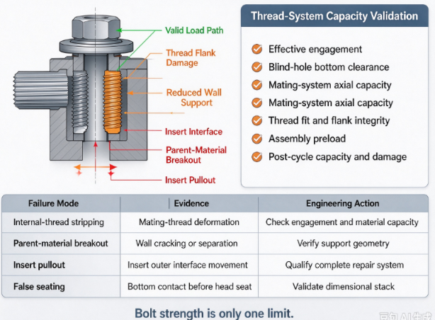
Failure: The bolt pulls out with damaged internal threads. Root Cause: Mating-material resistance and effective engagement are insufficient for the developed preload or service force. Engineering Consequence: Clamp force and attachment restraint disappear. Prevention: Compare competing capacities and qualify the actual tapped component rather than use bolt tensile strength as the joint rating.
Failure: Tightening torque rises before the head properly clamps the stack. Root Cause: Bolt length, usable depth, or trapped material eliminates the required tip clearance. Engineering Consequence: The connection passes a torque check but opens under service demand. Prevention: Verify the dimensional stack, usable depth, cleanliness, and seating response.
Failure: Assembly resistance is abnormal and later inspection reveals damaged flanks. Root Cause: Misaligned initial engagement forces incompatible flank contact and plastically damages the entry region. Engineering Consequence: Usable engagement and torque–clamp behavior become unreliable. Prevention: Control starting alignment and reject abnormal assembly signatures under an approved procedure.
Failure: The parent component cracks while the threads remain partly engaged. Root Cause: Insufficient surrounding wall or edge support cannot carry the local transferred forces, sometimes aggravated by eccentric loading. Engineering Consequence: Failure bypasses the thread-stripping mechanism assumed in design. Prevention: Assess surrounding geometry and test with representative component restraint.
Failure: The repaired threaded interface leaves the parent material with the bolt still engaged. Root Cause: The insert's outer load-transfer interface or installation condition lacks adequate verified capacity. Engineering Consequence: The repair loses structural function despite acceptable bolt threads. Prevention: Qualify the complete repaired configuration and control the installation process.
Failure: A bolt fractures near an engaged thread after assembly. Root Cause: Hydrogen-assisted cracking, fatigue from joint opening, or combined mechanisms act at a highly stressed region. Engineering Consequence: Improving engagement alone fails to address the actual cause. Prevention: Preserve fracture evidence and evaluate treatment history, stress state, and service cycling together.
Define installed engagement using usable external and internal threads rather than drilled depth.
Verify mating-material properties and compare bolt fracture, thread stripping, insert pullout, and parent-material failure.
Specify supporting wall geometry, edge conditions, grip length, and service load directions.
Require positive blind-hole clearance throughout the approved dimensional stack.
Qualify torque–clamp behavior for the actual mating component and friction condition.
Define thread-start alignment, seating confirmation, lubricant state, and abnormal-resistance rejection.
Identify the tightening tool, sequence, and any prevailing-torque contribution.
Specify repair and reuse restrictions with separate acceptance for changed configurations.
Identify corrosion, contamination, thermal exposure, and their effects on thread fit and material capacity.
Verify surface-treatment compatibility with tightening friction and hydrogen-risk controls.
Define hole cleanliness and fluid conditions before blind-hole assembly.
Confirm applicable standards and editions before specification; none were supplied here.
Require traceable dimensional, material, destructive-capacity, and torque–clamp records.
Define cyclic testing and crack inspection for impact-loaded applications.
Identify the authority approving repairs, material changes, and engagement modifications.
The supplied profile states that Ningbo yi teng construction machinery CO,LTD was established in 2005 and manufactures construction-machinery components and fasteners, with Pins as a principal product. Its listed activities include multiple fastener formats, custom components, Nuts, hydraulic accessories, and supply to overseas markets.
I evaluate any manufacturer's capability by asking whether it can verify the actual bolt–mating-component combination. Relevant evidence includes complete thread measurement, material traceability, heat-treatment control, post-coating fit checks, destructive failure-location records, and torque–clamp testing. The ability to distinguish thread stripping from parent-material breakout is essential when engineering a tapped housing.
No current certification is established by the supplied technical-standards field. Verify the correct holder, scope, and validity of any required certification before specifying it. A general management-system statement does not replace evidence of engagement capacity for a particular component.
The related product page should distinguish bolt geometries and mating-thread requirements so that effective engagement can be checked against the installed configuration.
Nominal hole depth cannot define effective engagement by itself. Entry chamfers, incomplete bottom threads, and the installed bolt position reduce usable overlap. Measure the load-bearing portions and verify their capacity with the actual mating material.
Increasing bolt length is acceptable only after confirming engagement, seating, and bottom clearance. The longer tip can contact a blind-hole obstruction before the members clamp. Thread runout and the dimensional stack must also remain compatible with the drawing.
A stronger nut or insert does not establish the capacity of every connection. Supporting material, outer insert retention, wall geometry, and bearing conditions may govern. Test the complete assembly and identify the actual failure mechanism.
A thread gauge cannot replace a pullout test when structural capacity requires verification. Gauging addresses dimensional features within its scope. Pullout or destructive assembly testing addresses material and load-transfer behavior, so the evidence serves different purposes.
Damaged internal threads require an approved repair assessment before reuse. Re-tapping can alter geometry and reduce supporting material. Verify the repaired engagement, assembly preload, and service capacity rather than assume the original qualification remains valid.
Share your project parameters for a technical review.
Contact person: Mr.Ren
Phone:0086-13958324455
Customer service: +86-0574 88065928
Email: Sales@zjbzj.com
Fax: +0086-0574 88065656

official website
Copyright @ Ningbo yi teng construction machinery CO,LTDmainly engaged in Blade Bolts Series, Hexagon bolt, and Bucket teeth. Welcome to inquire!
SitemapThis website uses cookies to ensure you get the best experience on our website.
 Español
 Portugues
 Pусский
 Français
 Deutsch
 日本語
 한국어
 العربية
 हिन्दी



 WhatsApp
 Phone
Comment
(0)