

A machine bracket can carry its nominal external load while a flexible mounting plate generates additional tension in the nearest fastener. The force applied to the equipment is not necessarily the force carried by each bolt. I evaluate bolts through the actual support geometry, contact behavior, and eccentric load path. This article examines bending, prying, thread reactions, and representative validation of attachments that experience combined loading.
The force carried by a bolt depends on how the assembled structure reacts to the external load. If the applied force acts away from the connection's effective reaction, it also produces a moment. The connected plate, bracket, housing, and fastener group must provide balancing reactions. Their flexibility and contact conditions determine where those reactions develop.
Preload initially compresses the contact and can help maintain the intended load path. An external separating force redistributes that compression and changes bolt tension. Where the plate remains in contact, the joint's stiffness influences the fastener response. Where contact opens, the reaction pattern changes. I therefore evaluate contact state as part of the loading mechanism rather than assuming an unchanged load distribution throughout service.
Tightening establishes bolt tension and a compressive pressure distribution beneath the connected structure.
An eccentric external force introduces both a direct load and a moment at the attachment.
The mounting plate and supporting structure deform according to their geometry and stiffness.
Contact pressure increases in some regions and decreases or disappears in others.
A plate edge or local contact region can become a reaction point that increases bolt tension through prying.
Fastener tension, shear, and bending must be assessed together with bearing and mating-thread reactions.
Prying is a structural interaction. A flexible plate can rotate about a remaining contact region, introducing an additional reaction that increases the force required at the fastener. Its magnitude cannot be inferred from the external force alone. Plate thickness, unsupported distance, bolt position, contact geometry, and support stiffness all influence the response.
Bolt bending can arise from misaligned bearing surfaces, plate rotation, transverse movement, or a reaction offset along the grip. A tensile material result does not establish the connection's resistance to this combined condition. I identify where the bolt is supported and where its cross section changes before assigning a representative load case.
No technical standards or verified specification values were supplied. The applicable analysis method, test document, clause, and acceptance limits require verification before specification.
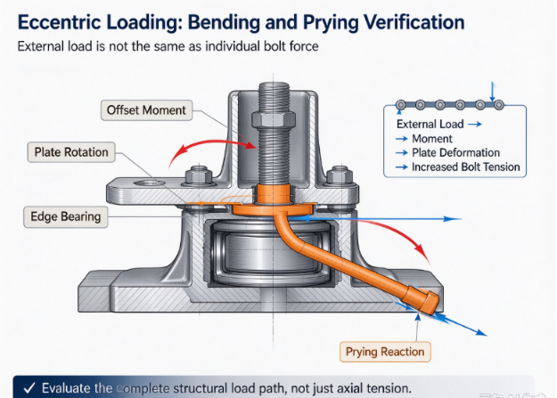
The attachment's structural components influence fastener demand as strongly as the fastener itself. I examine the load introduction point, mounting plate, supporting structure, bearing seats, and mating threads as a connected system. A test performed with an artificially rigid support may suppress the prying or rotation present in the installed machine.
Material specifications must identify the finished condition of each load-bearing component. Elastic stiffness, yielding behavior, bearing resistance, and fatigue-sensitive geometry require different evidence. The relevant parameter is not always the component's highest nominal strength; a flexible plate can increase bolt loading before it experiences obvious permanent damage.
| Component | Material Spec | Function | Failure Risk if Compromised |
|---|---|---|---|
| Bolt shank and transitions | Verify finished material, heat treatment, and geometry. | Carry tension, shear, and bending; verify combined-load response. | Local yielding or fatigue at a thread root or transition. |
| Mounting plate or bracket | Verify material condition, section geometry, and stiffness evidence. | Distribute external load; verify rotation and local bending. | Prying increases fastener tension. |
| Supporting housing or frame | Verify substrate material and local structural condition. | React the attachment load; verify support deformation. | Support flexibility changes contact and load sharing. |
| Head and bearing seat | Verify bearing material, flatness, and seating geometry. | Transfer the fastener reaction; verify alignment and indentation. | Edge bearing introduces bending or settlement. |
| Mating Nut or internal thread | Verify material and effective engagement. | React bolt tension; verify stripPing and local deformation. | Thread failure occurs before intended bolt capacity. |
| Contact interface | Verify surface geometry, finish, and treatment. | Provide compression and the intended transverse load path. | Opening, slip, or fretting changes structural behavior. |
Verify all parameters against current test reports and applicable standards before use in specifications.
A washer can distribute bearing load but cannot automatically correct structural misalignment. If the plate rotates or the bearing seat is inclined, the bolt may still experience an offset reaction. Any proposed support element must be evaluated for its seating behavior, stiffness, and effect on the complete load path.
The first task is to define the external load at the correct location and in the correct direction. I include the offset to the attachment, load reversals, transient events, and constraints imposed by neighboring components. A direct axial pull on a bolt cannot reproduce a bracket load that also bends the plate and changes its contact.
Analysis and testing should use compatible boundary conditions. A model may assume full contact, a rigid housing, or a symmetric fastener group. Those assumptions need justification against the installed geometry. The physical test should measure the responses most sensitive to them, such as plate rotation, local opening, bolt strain, and movement at the support.
| Parameter | Standard | Test Method | Acceptable Range | Implication if Out of Range |
|---|---|---|---|---|
| Applied load and eccentricity | Not supplied; verify governing document. | Measure force and its location relative to the attachment. | Verify the approved service and validation envelope. | The test does not represent the intended demand. |
| Initial preload | Not supplied; verify governing document. | Correlate assembly settings with measured force or extension. | Verify the approved preload interval. | Premature opening or excessive initial loading. |
| Bolt combined-load response | Not supplied; verify governing document. | Use suitable strain measurements and validated structural assessment. | Verify the approved tension, shear, bending, and damage criteria. | Yielding or fatigue resistance is inadequate. |
| Plate rotation and contact opening | Not supplied; verify governing document. | Measure displacement at defined contact locations. | Verify the permitted structural and functional movement. | Prying or changed load distribution develops. |
| Mating-thread capacity | Not supplied; verify governing document. | Assess and test the actual material and effective engagement. | Verify the approved load capacity and failure mode. | Stripping or local thread deformation governs. |
| Cyclic damage and retained preload | Not supplied; verify governing document. | Apply representative load history and inspect the conditioned assembly. | Verify the required residual condition. | The attachment cannot maintain its intended function. |
Verify all parameters against current test reports and applicable standards before use in specifications.
Measurement placement matters when bending is present. A strain reading from one side of a bolt can combine axial and bending effects. It should not automatically be interpreted as uniform tensile stress. I choose a measurement arrangement capable of distinguishing the required responses and account for any geometric changes introduced by instrumentation.
Test fixtures also need their own stiffness and alignment assessment. A fixture that prevents bracket rotation can underrepresent prying. A misaligned actuator can introduce an unintended moment. The report must describe these conditions and show why the resulting response is relevant to the installed attachment.
The principal protection mechanism is a controlled structural load path. I seek a configuration in which contact, support, and fastener reactions remain within their approved conditions across the required load envelope. Increasing bolt strength alone does not remove plate flexibility, reaction eccentricity, or a weak internal thread. The assessment must identify the component and mechanism that actually limit the attachment.
Preload can delay contact opening, but its beneficial effect has an upper boundary. Excessive assembly force can indent a bearing seat, deform a plate, or overload mating threads. Where the contact remains compressed, an external load is shared through the relative stiffness of the fastener and joint. After local separation, that relationship changes. I therefore examine the transition in contact state and its effect on peak and cyclic bolt loading rather than assuming one stiffness relationship applies throughout.
Torque and actual preload must be established for the finished attachment. Dry, lubricated, plated, and reused conditions can produce different force levels from the same torque setting. An eccentric structure makes this variation important because a low-preload specimen may open earlier, while a high-preload specimen can begin closer to a material limit. The validation should account for the assembly process's lower and upper conditions and the batch variability supported by measured torque-force data.
Bearing friction can also be influenced by seating geometry. A tilted surface or edge contact can cause abnormal rotational resistance during tightening while introducing a bending reaction beneath the head. I verify full seating and local bearing condition before interpreting the torque history. A normal final setting does not establish that the bolt is axially loaded or that the plate has achieved its intended contact state.
Impact and fatigue validation must reproduce the actual load direction and structural response. A blade support, crusher bracket, or vehicle attachment can experience a changing moment as the applied force reverses. The grip length, bolt support locations, and threaded shear-plane position influence bending and combined stress. I track plate rotation, interface movement, retained preload, and damage through the exposure. The bolt's material designation cannot replace the assembled connection's cyclic evidence.
Contact slip creates another possible change in the load path. Before slip, transverse force may be transmitted through interface friction. After clearance is taken up, it may transfer through local bolt-to-hole bearing. That reaction can occur at a threaded region or an unsupported span and increase stress concentration. The engineering decision must therefore address whether slip is permitted, how it changes the force system, and whether the resulting configuration remains qualified.
Effective thread engagement must be assessed against the highest relevant fastener reaction, including prying. The external attachment force is not an adequate substitute for that reaction. I exclude chamfers and incomplete threads from the effective length, verify blind-hole bottom clearance, and identify the actual internal-thread material. The stripping capacity must be compared with the bolt's relevant loading capability and the validated demand at the mating interface.
A tensile pull test using an ideal nut can conceal a limitation in a housing or insert. Representative validation must use the actual mating geometry and support condition where those determine capacity. Plate rotation may also create nonuniform loading in the thread reaction region. The test report should identify whether failure occurred in the bolt, mating thread, supporting material, or fixture. Without that distinction, a reported peak force has an uncertain engineering meaning.
High-strength finished bolts require a separate review of delayed-fracture risk. Prying can create sustained tensile demand beyond the initial assembly load, and bending can create a higher local stress than a uniform axial estimate suggests. Where finishing processes introduce hydrogen into susceptible material, those stresses are relevant to delayed cracking. I review hardness, acid-cleaning and plating records, hydrogen-relief controls where applicable, sustained-load validation, and specimen traceability.
Corrosion performance must remain a separate acceptance question. A coating that performs well in an exposure test has not thereby demonstrated resistance to hydrogen-assisted cracking or fatigue under combined loading. Likewise, a successful static bracket test does not establish the response after coating damage, settlement, or environmental degradation. I connect each test to the mechanism it evaluates and state which operating conditions remain unvalidated.
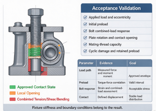
The nearest bolt carries unexpectedly high tension. A flexible mounting plate rotates about a remaining contact region and develops a prying reaction. The local bolt demand exceeds an estimate based only on the external load. Prevention requires evaluating plate flexibility, contact state, and load eccentricity, then verifying bolt reactions in a representative assembled test.
A crack initiates at a thread root or shank transition. Plate rotation or transverse movement bends the bolt while it also carries preload and service tension. The combined cyclic stress concentrates at the geometric transition. Prevention requires checking support locations, bearing alignment, threaded shear planes, and the actual cyclic load path.
The head bearing seat deforms on one side. An inclined or rotating contact introduces edge loading beneath the head or washer. Local indentation changes the reaction and can reduce preload. Prevention requires verifying seating geometry and bearing resistance under combined assembly and service loading.
The internal thread strips before the bolt reaches its expected capacity. The effective engagement or mating material cannot support the increased fastener reaction produced by eccentric loading. The attachment separates even though the bolt material remains intact. Prevention requires checking the actual mating component against peak reaction and confirming the failure mode through representative capacity evidence.
A laboratory test underestimates attachment demand. The fixture is substantially stiffer than the installed housing or suppresses the plate rotation responsible for prying. The specimen passes under an unrepresentative load path. Prevention requires documenting boundary conditions and correlating fixture response with the real supporting structure.
Local contact opening creates progressive fatigue damage. Insufficient retained compression permits repeated separation, increasing load variation in the fastener and movement at the plate. Prevention requires validating the lowest relevant retained-preload condition and the complete load history, including settlement and any permitted interface motion.
Structural requirements
Define the applied forces, moments, load locations, reversals, and relevant operating combinations.
Identify mounting-plate flexibility, support stiffness, contact geometry, and possible prying reaction points.
Verify fastener demand under the approved combination of tension, shear, and bending.
Specify effective thread engagement, bearing alignment, hole clearance, and the location of threaded shear planes.
Drive specifications
Define the assembly method and the verified preload interval for the finished friction condition.
Require torque-force correlation using the actual bearing arrangement and mating threads.
Define seating verification and the response to abnormal resistance or plate distortion during assembly.
Identify permitted reassembly conditions and any required reassessment of friction and contact.
Environmental requirements
Define impact, cyclic loading, temperature, and exposure conditions that can change contact or preload.
Require examination of coating damage, fretting, bearing indentation, and permanent structural deformation.
Verify surface-treatment compatibility with the material condition and sustained combined stress.
Safety standards and validation
Confirm the governing standard, analysis method, and clause before specifying compliance.
Require test boundary conditions that represent the installed load introduction and supporting structure.
Define acceptable contact movement, residual preload, component damage, and observed failure modes.
Require traceable material, finishing, dimensional, assembly, and test records for the validated configuration.
The specification should identify the assumptions controlling the fastener reaction. Changes in load offset, plate section, mounting location, supporting housing, or contact geometry can invalidate the original assessment. Such changes require an engineering comparison to the validated configuration before the previous acceptance is transferred.
For Ningbo yi teng construction machinery CO,LTD, the bolts product page should identify finished geometry and material evidence that can support assessment of the intended eccentric attachment.
I evaluate any manufacturer's ability to connect component reports with the actual assembled load path. Relevant capability includes dimensional control of bearing transitions, traceable material condition, configuration-specific thread assessment, and testing that distinguishes axial tension from bending. The engineering record should explain fixture stiffness and observed failure location.
No certification or standard compliance is established by the information supplied here. Any required certification must have verified scope and current status before specification. A sound technical review also states where the fastener data ends and where the bracket, housing, and complete attachment require additional validation.
Only when the verified geometry, stiffness, contact, and loading support that distribution. Eccentric force introduces a moment, and flexible components can alter individual reactions. Equal division is therefore an assumption that requires justification.
No, thickness is only one influence on the structural response. Unsupported distance, bolt position, support stiffness, and contact geometry also matter. The revised configuration needs analysis or testing that confirms its actual reactions.
No, uniform tensile loading does not reproduce cyclic bending and its stress concentration. Support locations and geometric transitions influence the combined response. Representative assembled loading is needed when bending is part of service demand.
The fastener reaction can exceed the apparent external force because of preload and structural prying. Limited effective engagement or weak mating material can further reduce capacity. The comparison must use the actual thread reaction and mating-component evidence.
It requires reassessment when it can alter stiffness, contact, thread capacity, or the load path. A more flexible housing may increase plate rotation or redistribute fastener demand. The previous test remains applicable only if the transfer is technically justified.
Share your project parameters for a technical review.
Contact person: Mr.Ren
Phone:0086-13958324455
Customer service: +86-0574 88065928
Email: Sales@zjbzj.com
Fax: +0086-0574 88065656

official website
Copyright @ Ningbo yi teng construction machinery CO,LTDmainly engaged in Blade Bolts Series, Hexagon bolt, and Bucket teeth. Welcome to inquire!
SitemapThis website uses cookies to ensure you get the best experience on our website.
 Español
 Portugues
 Pусский
 Français
 Deutsch
 日本語
 한국어
 العربية
 हिन्दी



 WhatsApp
 Phone
Comment
(0)