

A bolted crusher liner can reach its assembly setting while remaining poorly supported against the shell or backing system. Repeated material impact then makes the liner rock and changes the fastener reaction. I evaluate bolts through the liner, support, bearing seats, and service-wear configuration. This article addresses bolted liner attachments rather than assuming that every crusher uses the same retention mechanism or assembly procedure.
A bolted liner attachment maintains the intended relationship between a wear component and its supporting structure. The fasteners can provide compression, resist separation, or participate in a specified mechanical retention arrangement. The exact function depends on the crusher and liner design. I identify the actual arrangement before applying general bolted-joint reasoning.
The liner receives localized forces from processed material. Those forces should pass through the designed support into the machine structure. If the liner lacks support, it can flex or rock, transferring additional reaction into the fasteners. A bolt that was intended mainly to maintain seating can then carry repeated bending or tensile demand. This change is not established by the installation torque record.
Identify the bolted liner configuration, support system, shell geometry, and specified retention hardware.
Verify that the liner reaches its intended support condition without unauthorized gaps or trapped material.
Confirm head-seat engagement and the mating fastener geometry.
Apply the approved assembly process to establish the required physical retention state.
Verify the completed liner position, contact condition, and fastener engagement.
Evaluate the retained condition under representative loading, exposure, and permitted wear geometry.
Some designs include an intermediate support or backing material. Its role must be established from the actual engineering documentation. It may fill a space, distribute support, or perform another defined function. I do not assume that its presence eliminates liner movement or that its deformation is irrelevant to fastener preload.
Wear changes the liner's mass, section, working surface, and sometimes the exposure of its attachment features. An intact bolt at the start of service can later have reduced support or protection. The validation must identify which stages of the permitted wear condition are represented and what observations trigger further assessment.
No technical standards or verified specification appendix were supplied. The liner attachment procedure, material limits, assembly values, and applicable test clauses require verification before specification.
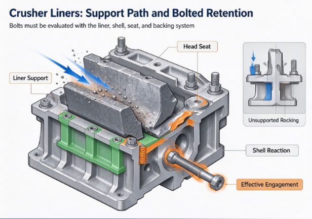
The investigation must include components that determine support and retention. A finished bolt report cannot establish that the liner is properly seated or that the shell provides the intended reaction. I require traceable descriptions of the actual wear component, support condition, and fastener arrangement.
| Component | Material Spec | Function | Failure Risk if Compromised |
|---|---|---|---|
| Bolt shank and transitions | Verify finished material, heat treatment, hardness, and geometry. | Maintain retention and carry specified reactions; verify combined-load response. | Yielding, bending fatigue, or fracture. |
| Head and liner seat | Verify finished profiles and local liner material condition. | Transfer the fastener reaction; verify fit and bearing resistance. | Seat deformation or incomplete engagement. |
| Mating Nut or internal thread | Verify material and effective engagement. | React tension; verify stripPing and deformation capacity. | Clamp loss or separation. |
| Wear liner | Verify material condition and permitted service geometry. | Receive working forces and transfer them to support. | Rocking, cracking, or changed fastener demand. |
| Shell and support interface | Verify structural material, geometry, and contact condition. | Provide the intended load reaction; verify stiffness and support. | Concentrated loading or unsupported liner motion. |
| Specified backing or support element | Verify material identity and finished or conditioned state where present. | Perform the documented support function; verify deformation and stability. | Settlement or incomplete support changes retention. |
Verify all parameters against current test reports and applicable standards before use in specifications.
The shell's service condition can be as important as the replacement liner. Residual material, worn contact regions, or distorted bearing features can prevent the new component from reproducing the qualified support. I examine the supporting structure before attributing abnormal assembly or early movement to the fastener alone.
Special head or locking arrangements need configuration-specific evidence. Their purpose may include preventing rotation during assembly, establishing a bearing reaction, or limiting separation. Those functions must be identified individually. A feature that assists installation should not automatically be credited with preventing all movement throughout the wear cycle.
Validation begins with a complete configuration record. Crusher type, liner location, attachment geometry, support system, fastener stack, and permitted wear condition define the application. Different liner locations can experience different force directions and access constraints. A result from one arrangement cannot be transferred solely because the bolts have the same nominal size.
I define test outputs around support and retention. These can include generated preload where preload is part of the design, liner movement, bearing-seat deformation, effective engagement, retained force, and post-exposure damage. The assembly record must also identify whether support material has reached its specified condition before the final retention measurement.
| Parameter | Standard | Test Method | Acceptable Range | Implication if Out of Range |
|---|---|---|---|---|
| Liner support condition | Not supplied; verify governing document. | Inspect and measure contact or backing condition using the approved method. | Verify the configuration-specific support requirement. | Rocking or concentrated impact reaction develops. |
| Head-seat engagement | Not supplied; verify governing document. | Measure profiles and verify assembled bearing contact. | Verify approved fit and deformation limits. | Retention force acts through an unintended contact. |
| Generated preload | Not supplied; verify governing document. | Correlate the defined tightening process with force or extension where applicable. | Verify the approved assembly-force interval. | Insufficient retention or component overload. |
| Liner movement | Not supplied; verify governing document. | Measure displacement under representative loading. | Verify the permitted functional movement. | Fastener bending or support wear progresses. |
| Effective thread capacity | Not supplied; verify governing document. | Assess and test actual mating material and engagement. | Verify approved capacity and failure criteria. | Thread failure governs the attachment. |
| Condition after cyclic exposure | Not supplied; verify governing document. | Inspect retained force, cracks, wear, and permanent deformation. | Verify the required residual condition. | The validated retention function is not maintained. |
Verify all parameters against current test reports and applicable standards before use in specifications.
Representative loading must account for the actual support stiffness. A fixture that fully supports the liner can suppress the rocking present in the machine. A fixture that leaves an artificial gap can create a different failure mechanism. I document contact and support so that the test can be interpreted against the installed arrangement.
The report must also define the timing of measurements and interventions. Retightening, backing replacement, liner repositioning, and cleaning can change the mechanical state. The original result and the post-intervention result should remain separate. This makes the observed retention history reviewable and prevents a recovery action from concealing the initial failure.
The main protection mechanism is a stable support path that keeps the liner and fasteners performing their intended functions. The liner should not be assumed to bridge an unqualified gap simply because the bolts can pull it toward the shell. Forced seating can introduce bending or local stress into the wear component. I verify support before assigning fastener capacity to compensate for missing contact.
When an intermediate material is specified, its condition is part of the assembly. Its thickness, placement, deformation, and interaction with the liner and shell can affect retention. A compressible or incompletely conditioned layer can change the stack after tightening. The relevant evidence must show the assembled support state and its behavior under the intended exposure. A generic description such as backing material does not define that behavior.
Torque and actual preload require correlation with the finished attachment where the design relies on preload. Dry, lubricated, plated, and reused hardware can produce different force from the same setting. Abrasive contamination and service fluids can alter both thread and bearing resistance. I assess measured torque-force behavior and specimen variation using the actual head seat, nut, support hardware, and permitted friction condition.
The lower assembly condition must maintain the intended retention after support changes and representative exposure. The upper condition must protect the bolt, liner seat, mating threads, and shell reaction. Applying more torque to overcome uncertain seating can damage a liner or thread without establishing stable contact. The process must satisfy both boundaries using configuration-specific evidence rather than treating tool completion as proof of useful clamp force.
Impact and fatigue validation must reproduce force direction, grip, support, and any threaded shear plane. An unsupported liner can rotate and bend the fastener, while a supported liner can distribute the reaction differently. I measure liner movement alongside retained preload and examine cracks after cyclic exposure. A fastener strength designation does not establish fatigue resistance for a liner attachment whose support and working loads differ from the component test.
Abrasive wear can alter the attachment during service. Material loss around a head seat can reduce bearing support, and exposed hardware can lose protective coating. The specification needs a defined wear condition and an inspection basis connected to the retention mechanism. Fastener presence is insufficient if the liner has begun moving or the head no longer bears on the qualified seat. Remaining geometry must be assessed against the current evidence.
Effective engagement must be checked within the complete liner stack. Added support elements, changed liner thickness, or replacement nut geometry can alter available engaged length. Chamfers and incomplete threads must be excluded from the effective region. Blind-hole bottom clearance must be verified where applicable. I compare actual thread-stripping capacity with the bolt's relevant capability and the maximum approved assembly and operating reaction.
Capacity testing must preserve the actual mating component and support condition. A laboratory nut may conceal the limitation of a tapped shell feature, insert, or service-damaged thread. The report should identify whether the observed failure occurred in the bolt, engaged threads, surrounding structure, or fixture. If a repair is permitted, it needs representative evidence for its geometry and material rather than a visual confirmation that a fastener can be installed.
Surface treatment introduces a separate delayed-fracture risk for susceptible high-strength material. Hydrogen can enter during acid cleaning or electroplating, and sustained tension can support delayed cracking. I review finished hardness, processing records, hydrogen-relief controls where applicable, sustained-load validation, and batch traceability. Corrosion exposure, coating thickness, or appearance cannot establish resistance to hydrogen-assisted fracture.
The inspection plan should preserve evidence of support and movement. Fretting, contact impressions, head-seat damage, and liner position can help explain the failure sequence. Cleaning or repositioning before documentation can remove that information. I define which observations require further assessment and keep the physical evidence linked to assembly and service records. Corrective validation then addresses the demonstrated mechanism rather than merely replacing a broken bolt.
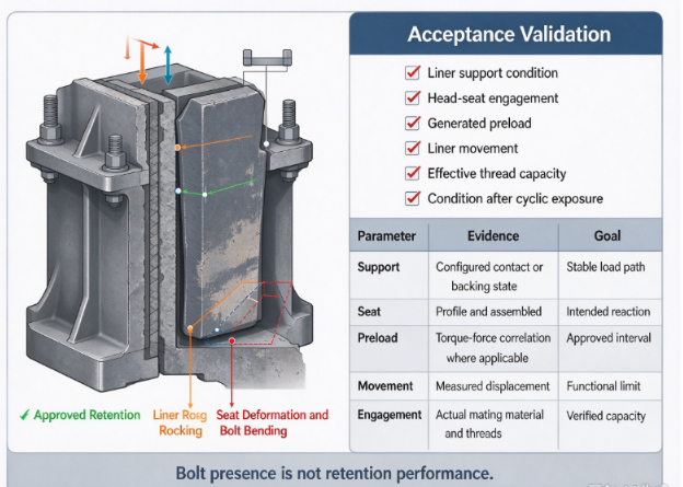
The liner rocks after installation. Incomplete shell contact or an unstable support layer permits rotation under material impact. Fastener reactions become cyclic and concentrated. Prevention requires support verification and representative movement testing of the complete attachment.
A head seat deforms while the bolt remains intact. Mismatched bearing geometry or local liner damage concentrates the reaction. The retention stack changes and force decreases. Prevention requires profile inspection and bearing validation at the upper approved assembly condition.
A bolt fractures through cyclic bending. Liner movement imposes alternating reaction across the grip or a threaded region. A crack grows before final separation. Prevention requires controlling support, measuring movement, and reproducing the relevant load direction during validation.
The assembly setting is reached without the intended retention state. Contaminated threads, abnormal seat contact, or locking resistance consumes torque. Prevention requires physical seating verification and torque-force correlation for the approved finished condition.
Service wear removes qualified bearing support. Material loss around an attachment changes its contact geometry. A new-part result no longer represents the liner. Prevention requires defined wear-stage acceptance and inspection linked to the actual retention mechanism.
A delayed fracture is misclassified as impact overload. Susceptible material and hydrogen exposure cause cracking under sustained tension before a later operating event completes separation. Prevention requires preserving fracture evidence and reviewing the finishing history independently of the final event.
Structural requirements
Identify the crusher location, liner design, shell support, intermediate material, and complete attachment configuration.
Define the intended retention function and the permitted liner movement.
Verify head-seat geometry, grip support, effective engagement, and threaded shear-plane location.
Specify the new and permitted worn conditions covered by the validation.
Drive specifications
Define assembly preparation, support conditioning, tightening method, and seating verification.
Require torque-force correlation where preload forms part of the retention design.
Identify approved lubrication, contamination, reassembly, and hardware-reuse conditions.
Define the response to abnormal resistance, incomplete support, and interrupted installation.
Environmental requirements
Define representative impact directions, cyclic loading, abrasive exposure, and relevant temperature conditions.
Verify the support material's behavior in its specified assembled state.
Require inspection of head-seat wear, coating damage, liner movement, and cracks after exposure.
Safety standards and validation
Confirm the applicable technical document and clause before specifying compliance or numerical limits.
Define acceptance separately for support, retention force, movement, engagement, and damage.
Preserve material, finishing, assembly, service, and specimen identity through traceable records.
Require engineering review after liner, support, shell, fastener-stack, or process changes.
The specification should state which attachment type it validates. Bolted liners, other mechanical retention arrangements, and pressure-supported components cannot share an acceptance procedure solely because they belong to the same crusher. The complete load path and maintenance configuration determine the applicable evidence.
For Ningbo yi teng construction machinery CO,LTD, the bolts product page should identify finished crusher-fastener geometry and the material and assembly evidence relevant to the proposed bolted liner attachment.
I evaluate any manufacturer's ability to support configuration-specific bearing, thread, and friction assessment. Useful records include finished dimensions, traceable heat treatment, finishing history, and representative mating-component tests. The engineering report should identify fixture support and the actual observed failure mode.
Any required certification must have verified scope and current status before specification. A management-system record does not establish liner retention through its wear period. The useful capability is the ability to connect the finished fastener with the complete supported attachment and its validation limits.
Only if that load path is explicitly designed and validated. Pulling a liner across an unqualified gap can introduce bending and concentrated fastener reactions. Support condition must be assessed before assigning retention capacity.
No, abnormal friction or head contact can produce the reading without the intended support state. Seating and force generation require configuration-specific evidence. The completed liner position must also be checked.
Only when their relevant geometry, support, loading, and exposure are adequately represented. Different locations can impose different force directions and attachment reactions. The transfer basis must be documented.
No, its deformation can change the attachment's support or compressed stack. Its intended role and conditioned state require verification. The fastener test must represent that state where it affects retention.
Yes, unacceptable movement or damage can occur without complete separation. Hardware presence does not establish stable support or acceptable fatigue behavior. The acceptance decision must include the required joint function.
Share your project parameters for a technical review.
Contact person: Mr.Ren
Phone:0086-13958324455
Customer service: +86-0574 88065928
Email: Sales@zjbzj.com
Fax: +0086-0574 88065656

official website
Copyright @ Ningbo yi teng construction machinery CO,LTDmainly engaged in Blade Bolts Series, Hexagon bolt, and Bucket teeth. Welcome to inquire!
SitemapThis website uses cookies to ensure you get the best experience on our website.
 Español
 Portugues
 Pусский
 Français
 Deutsch
 日本語
 한국어
 العربية
 हिन्दी



 WhatsApp
 Phone
Comment
(0)